


Ultrasonic thickness measurement is one of the most widely used NDT techniques in the world. It makes it possible to measure the thickness of a material from one side only, with no cuts, holes or other alterations. This basic guide explains the physical principles, the components of an ultrasonic instrument, the critical parameters and how they translate into a reading on the display. It is intended as an introduction for NDT inspectors at the start of their training and as a refresher for experienced technicians.

The physical principle: pulse and echo
The principle is analogous to sonar. A piezoelectric transducer generates a short ultrasonic pulse (typically in the 1-20 MHz range) that travels through the material at that material’s characteristic velocity. When the pulse meets a boundary surface (back wall, flaw, interface), part of the energy returns as an echo. The transducer picks up the echo and converts it into an electrical signal.
By measuring the time of flight between the transmitted pulse and the received echo, and knowing the speed of sound in the material, the instrument calculates the distance with the formula:

Need help choosing the right product?
t = v × Δt / 2
where the factor of 2 accounts for the pulse travelling the distance twice: there and back.
Components of an ultrasonic instrument

A complete gauge consists of:
- Pulser: produces the electrical voltage that excites the transducer
- Transducer (probe): contains a piezoelectric crystal that converts electrical energy into mechanical energy (transmission) and vice versa (reception)
- Acoustic couplant: gel or liquid between the probe and the part, needed to transfer the ultrasonic energy
- Receiver and amplifier: acquires the return echo and amplifies it
- Filter and digitiser: removes noise and converts the analogue signal into digital
- Processor and firmware: analyses the waveform, identifies the relevant echoes and calculates the thickness
- Display: shows the numerical value and, on the advanced models, the A-Scan waveform
- Memory (data logger): stores the readings for later download
The role of the transducer

The transducer is the component that makes the difference between an accurate measurement and a wrong one. The main types are:
- Dual element: two separate crystals (transmitter and receiver), used in corrosion gauges
- Single element: a single crystal, used in precision gauges and flaw detectors
- Angled shear wave: mounted on wedges to generate transverse waves, used in weld inspection
- High temperature: special probes for hot surfaces
- Underwater: waterproof probes for measurements in water
For more detail, see the guide to choosing the transducer.
Speed of sound and calibration
The speed of sound is the critical parameter of the measurement. It varies from material to material and even within the same material depending on composition and treatment. Indicative values:
- Carbon steel: ~5900 m/s
- Stainless steel: ~5700-5800 m/s
- Aluminium: ~6300 m/s
- Titanium (Ti-6Al-4V): ~6100 m/s
- Copper: ~4700 m/s
- Brass: ~4400 m/s
- HDPE (plastic): ~2200 m/s
- Cast iron: ~5000-5600 m/s (variable)
Before every measurement the instrument must be calibrated. For more detail, see 1-point vs 2-point calibration.
What the operator sees: numerical display and A-Scan

The Dakota instruments offer several display modes:
- Numerical display: value in mm or inches, immediate to read
- Bar graph: graphic representation of the value for reading at a glance
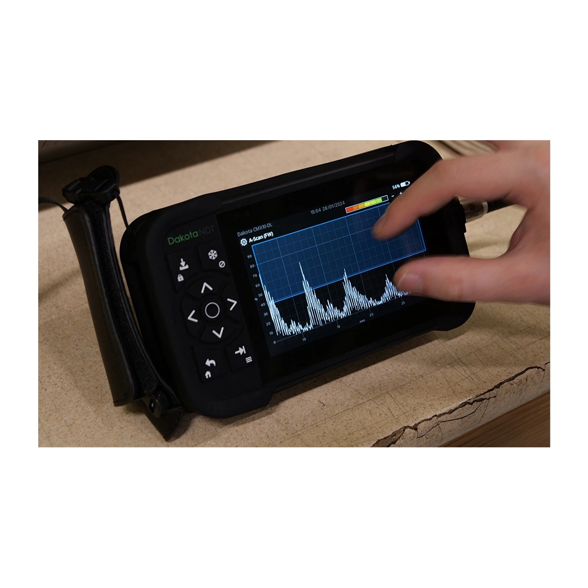
- A-Scan: waveform of the ultrasonic signal, showing the echoes with their position in time and their amplitude — essential for validating the measurement
- B-Scan: 2D cross-section representation of the thickness profile along a scan line
- Run Chart: graph of the readings over time, to follow a continuous scan
- Differential Mode: shows the difference from a reference value
Accuracy, resolution and repeatability
Three parameters not to be confused:
- Resolution: the smallest figure the instrument displays (0.01 mm as standard, 0.001 mm on the Precision models)
- Accuracy: how close the reading is to the true value. Typically ±0.1 mm over the standard range, ±0.05 mm on the top-of-the-range models
- Repeatability: how far repeated readings at the same point give the same value. Typically better than the resolution if the instrument is well calibrated
Reference standards
Ultrasonic thickness measurement is governed by international standards. The Dakota instruments are declared compliant with:
- EN 14127: harmonised European standard for the measurement procedure
- ASTM E797: American standard
- EN 15317: qualification of the instrument
- EN 12668-1: for flaw detectors
For more detail, see NDT standards for thickness measurement.
For further information, training courses and the selection of the instrument best suited to your NDT inspection requirements, contact our technical department.